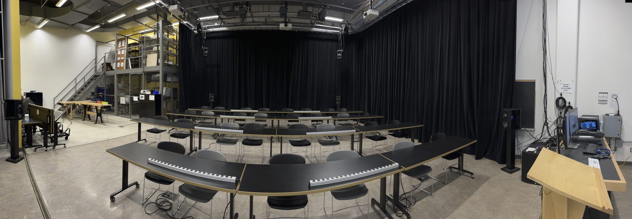
Room setup: default State
The following image shows the default state of this room and how the room should be left at the end of class or Open Lab. The white projector screens should be put away into the wall slots. The black curtains should be closed along the walls. 4 Rows of tables with 2 power bars setup on each row. The default state for the Instructor’s podium is show below.
A floor plan of the space is available here: ACW103-FloorPlan
Instructor’s Station Podium
The Instructor’s podium can be switched between a laptop (via HDMI cable), Mac Studio, Alienware Windows PC, Doccam. The LCD Panel switches between all of these setups on the 2 Monitors and front projector. See images below.


On the LCD panel (code is 5065), select the source, the Desktop Monitor outputs and the Projector. Audio volume is also controlled via the LCD panel in the bottom right depending on your source.

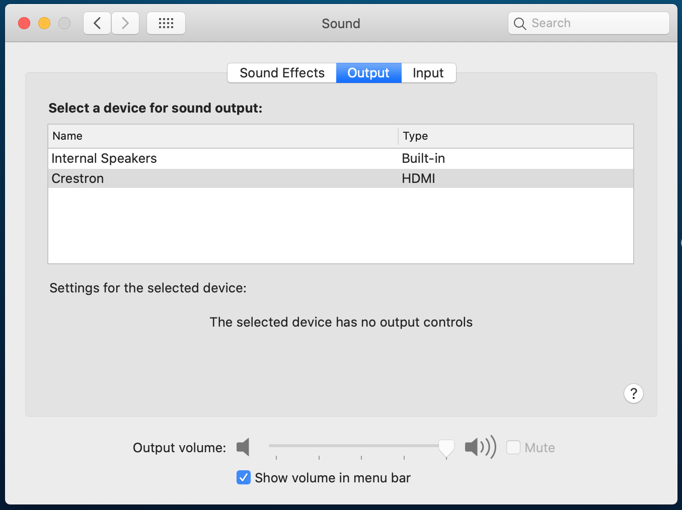
For audio output on your laptop, you must select Crestron in System Preferences -> Sound. On Windows 11, Settings -> Sound and select Crestron.
Projection System + Surround Sound
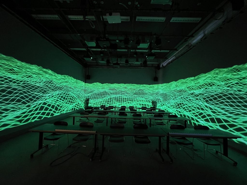
The Transmedia Lab has a 4 screen projection system, 9.2 channel audio system, Digital lights. The Alienware Windows PC in ACW103 has Max 9 RNBO and Touch Designer Educational installed and controls the projectors and sound system. Login to the computers using your Passport York account.
In order to use these systems, students must have received a demonstration by their Instructor during class.
IMPORTANT: ON THE ALIENWARE WINDOWS PC – SAVE ALL FILES AND PROJECTS TO DATA D: DRIVE. DO NOT SAVE FILES TO THE DESKTOP, AS THIS WILL FILL UP C: DRIVE AND APPLICATIONS MAY STOP WORKING PROPERLY.
Max 9 patches can be downloaded as a templates for controlling the Projection and Audio systems.
Touch Designer Educational version runs at resolutions of 1920×1080 and above. See online documentation for more information: https://derivative.ca/feature/high-performance-media-systems/74
Projector and Speaker Arrangement
The following two images show the 4 Projector and 11 Speaker arrangement in ACW103. The numbers correspond to the value of each Projector/Speaker in the setup.

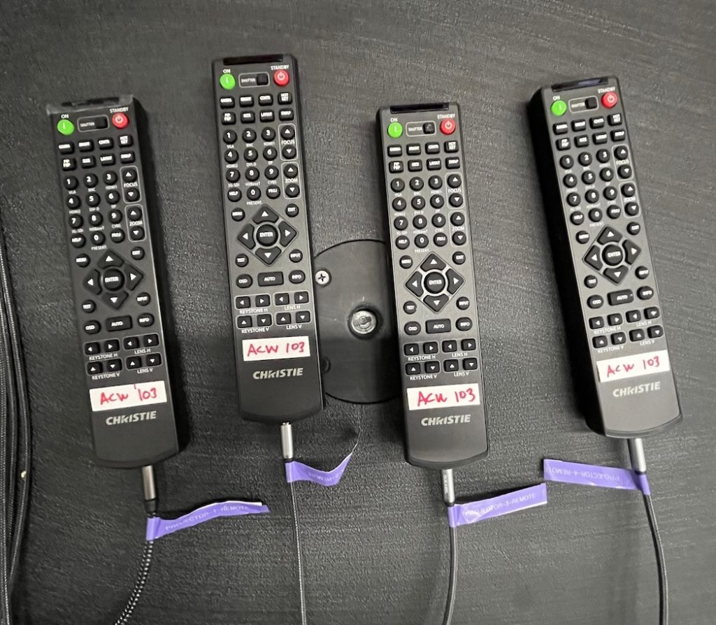
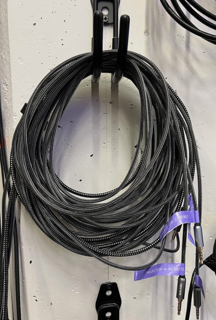
The 4x Christie DWU960-iS Projectors are individually controlled by a remote controller (Turning ON/OFF and minor lens position adjustments). Each remote is hardwired into the back of the projector via 3.5 mm cables hanging on hooks, to prevent communication crossovers. Each cable is numbered for the Projector they control, plug in the cables into their designated remote. See images below (Remotes hired-wired, numbered cables hanging on wall hooks)
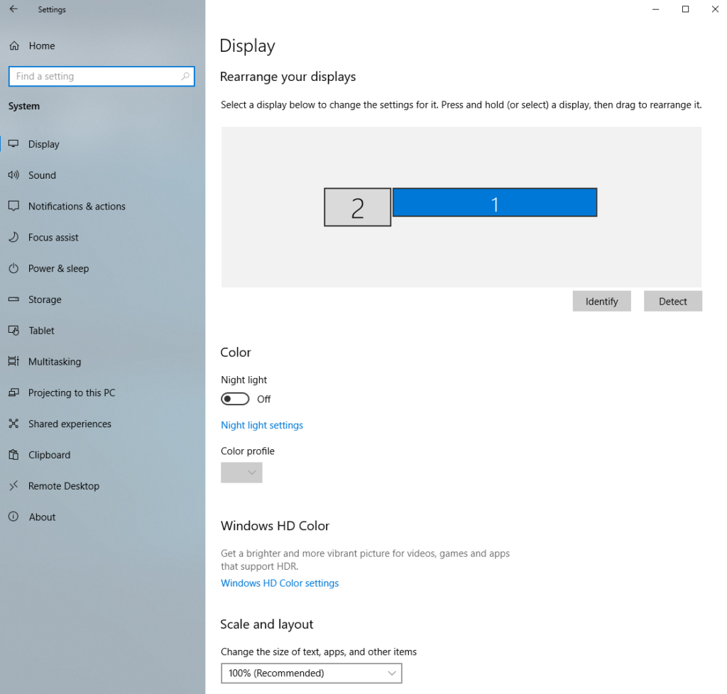
The projector arrangement is show in the image below. You can access this window on the PC by going to Settings -> Display. The leftmost display (shown as 2) should be the PC Monitor. All additional Projectors are listed as 1 . Note: The 4 projectors all register as display 1, in one long window (7680 x 1080) clockwise around the space. Return the Display layout to the one shown in the diagram.


Audio System
The 9.2 Channel Sound system is controlled by a MOTU A024 interface. To turn on the audio interfaces, speakers and Behringer I/O Box, DMX controller box, turn on the amplifier at top of the rack (See image below. Red circle illustrates the power button to turn on audio components).

The MOTU 24Ao interface is connected to the PC via USB. All sound output to the 9.2 speakers is done via Max/MSP.
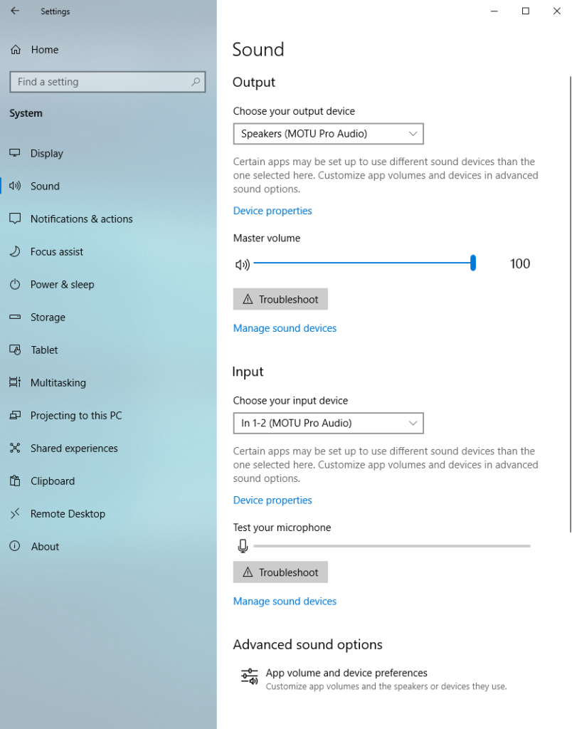
MOTU audio drivers here: MOTU 24Ao interface drivers. You can access the Sound settings on the PC via Settings -> Sound. The output should be set to Speakers (MOTU Pro Audio) and the input shoud be In 1-2 (MOTU Pro Audio)
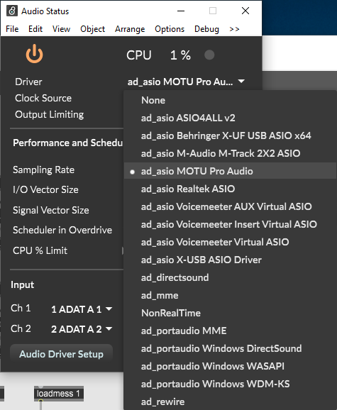
To output sound from Max/MSP/Jitter to the Speakers, select the MOTU 24Ao via Options -> Audio Status. The Driver drop-down menu should be set to “ad_asio MOTU Pro Audio”. You can output audio signals from a dac~ object with 11 outputs.
Extending the audio system
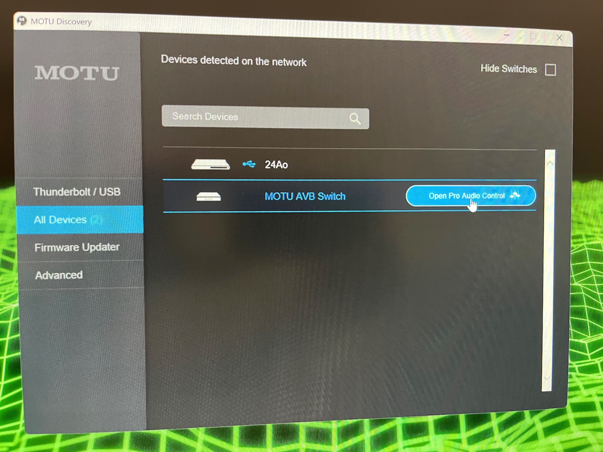
If required, the audio system can be expanded by attaching additional audio devices into the MOTU 24Ao. This is done via the MOTU AVB Switch shown below highlighted by the red circle.
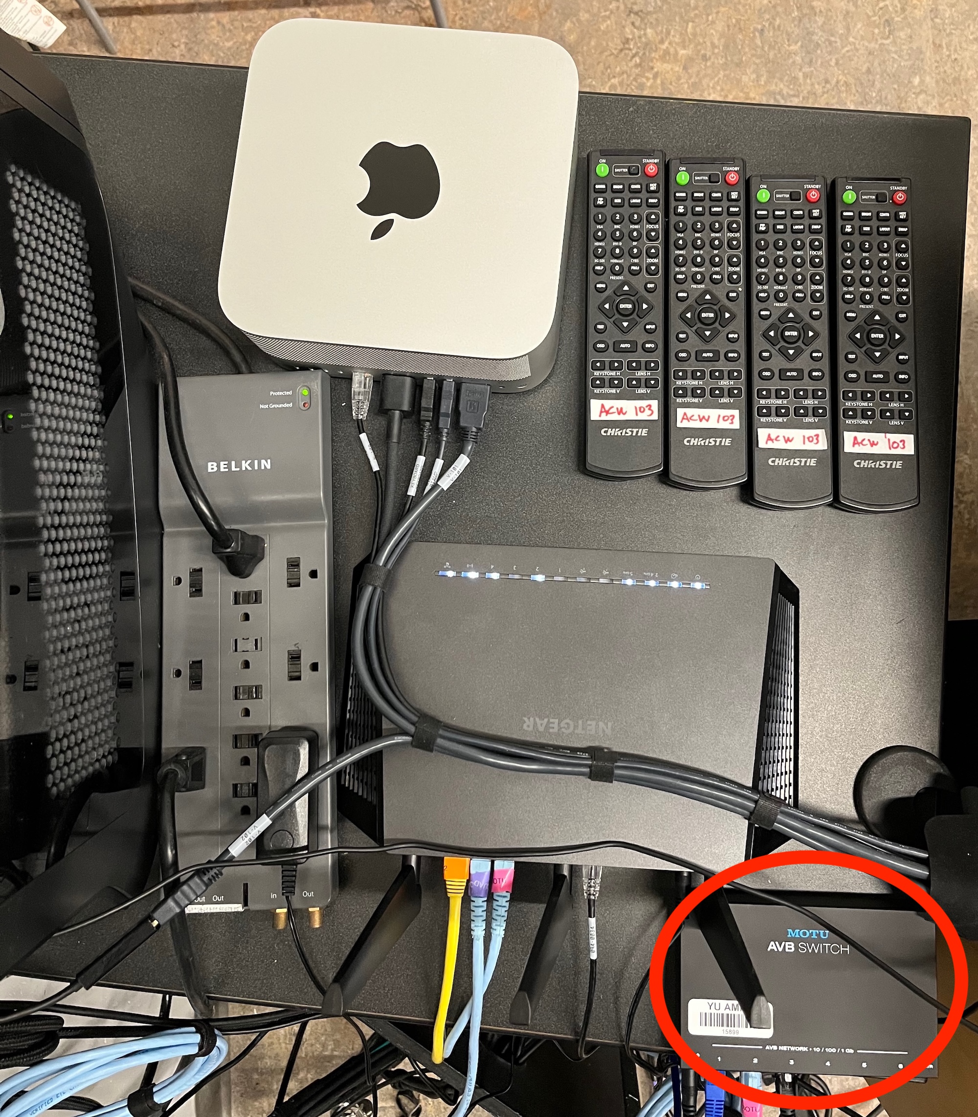
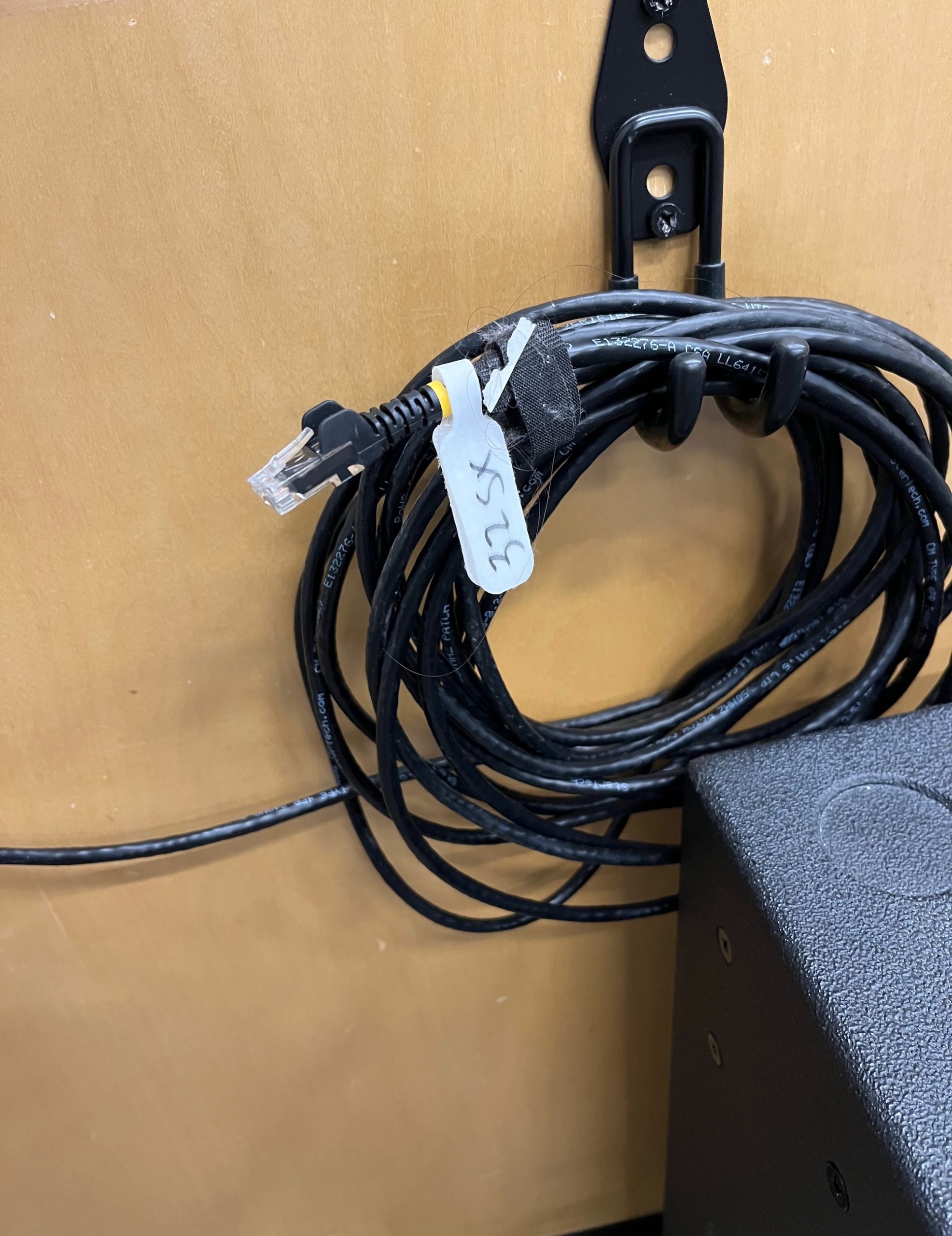
Audio devices can be connected to vacant Ethernet ports on the MOTU AVB Switch. An Ethernet cable is permanently available on the hook above the subwoofer show below. Attach your device to the Ethernet cable, and it will show up in The MOTU Discovery software on the Windows PC.
Select your audio device in All Devices tab show below, and make changes within MOTU Discovery software. These settings are at the discretion of the Faculty member who has shown you how to add devices to the audio system.